
Diagnostic Radiology
The Role of Medical Physics in Diagnostic X-ray Services
The role of Medical Physics in medicine began with the discovery of X-rays by Roentgen in 1895 and their subsequent use in diagnosis. The physicists’ role is therefore to apply scientific expertise to the assessment and development of imaging equipment, the monitoring and control of radiation doses to patients, staff and the general public and the overall efficacy of imaging techniques.
1. Quality Assurance
In the context of X-ray imaging, QA refers to those activities which ensure that suitable X-ray imaging systems are purchase and their performance matches specified criteria. QA can be considered as:
1.1 Identification, specification and choice of imaging equipments
The physicist, who is a member of the team responsible for choosing new equipment, provides advice on the performance characteristics of imaging systems and comments on the suitability of equipment for the proposed usage.The physicist also establishes a liaison between the X-ray manufacturer and the users as an impartial and objective assessor of the equipment.
1.2 Acceptance testing and performance evaluation
An objective assessment of equipment performance in a clinical environment is made. This complements factory laboratory testing and the largely subjective radiological assessment. The results of such as assessment of new equipment determine, along with other factors, whether or not the equipment is acceptable for clinical use.
Performance evaluation deals with the relationship between dose and image quality and clinical application. Digital techniques such as Computed Tomography (CT), demand extra expertise in computing and data handling.
The introduction of digital imaging in a wider context (digital fluorography and digital radiography) requires the physicist to contribute to the evaluation and analysis of digital images and in the longer term in the establishment of “digital department”.
1.2.1 Acceptance tests for Radiographic and Fluoroscopic Systems:Non-invasive technique
- Generator calibration:
kVp:
Many noninvasive high voltage measuring systems are available. All systems estimate the kVp based on a penetrometer measurement technique. The X-ray beam is attenuated through a pair of metal filter and a ratio signal proportional to the instantaneous tube voltage is calculated.
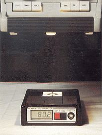
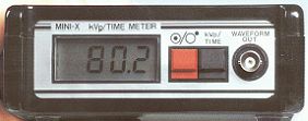 Setup of a kVp/Time meter
Tube current (mA):
Tube current may be inferred by measuring mAs and dividing by the length of exposure duration. Reasonable accuracy is achieved at longer exposure times if the accuracy of the exposure time has been established.
Exposure time:
Many noninvasive test devices, such as the one shown above, are available for measurement of exposure duration. Most of this devices use photodiode detectors and base the measured time on a threshold crossing technique. These devices may be exposure or exposure rate dependent and may not provide good results for exposure times below 15-20 milliseconds. - X-ray tube focal spot size:
Slit camera method:
A slit camera with a slit of 1 cm long and 10 um in width is used to provide images of the focal spot on a film in both directions parallel to and perpendicular to the anode-cathode axis.
Star phantom method:
The star phantom consists of an array of alternating highly absorbing and low absorbing wedges. The star phantom is placed normal to and centered on to the central axis of the X-ray beam, and a radiograph is taken. The dimension of the focal spot can be calculated by measuring the distances of the blurring zones in both directions parallel to and perpendicular to the cathode-anode axis.
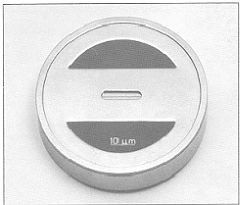
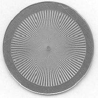
Slit camera Star phantom 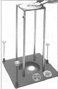
Left figure is stand for slit camera and star phantom set up 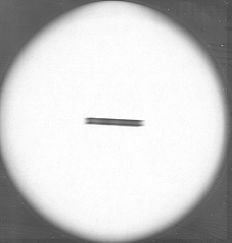
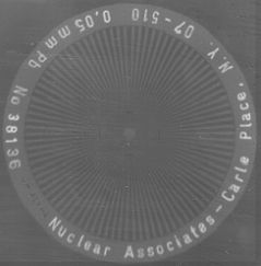
Image of a slit camera Image of a star phantom - Beam quality, HVL:
The beam quality is measured by means of Half Value Layer (HVL). A set of pure aluminium filters (type 1100 aluminium) of different thicknesses from0.1 mm to 1 mm is used:
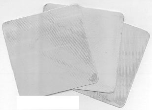
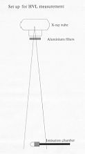
An ionisation chamber is placed in the X-ray beam at about 100 cm from the X-ray source. The exposure parameters are fixed to 80 kVp, 100 mAs. The exposures are measured both without filter and by adding filters. The thickness of aluminium that is required to cut the output to half is the HVL. - X-ray wave form analysis:
The kV waveforms for various generator system are as shown below on the left:

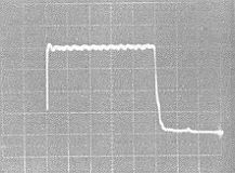
Waveforms for different generators Typical 3 phase generator waveform
They can be measured by means of a voltage divider connected to an oscilloscope, which is an invasive technique. Typical output from the oscilloscope is as shown above on the right. - Collimation:
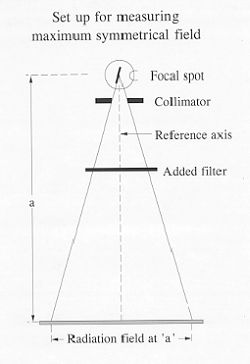
Maximum symmetrical radiation field:
One of the most important factors in selecting an X-ray tube is the radiation field coverage at a specific distance form the focal spot.
The NEMA standards define a test procedure to identify the size of a radiation field at a distance 'a' from the focal spot, symmetrical with respect to the reference axis and with the field edges parallel to the major axes x and y. A distribution of relative air kerma rate along the perimeter of not less than 25%as compared to the maximum density in the measuring plane, shall be achieved.
The IEC standards define the maximum symmetrical radiation field as the greatest field at a distance ‘a’ from the focal spot, with its edges parallel to the major axes, in which the distribution of air kerma along the major axes x and y does not fall by more than 70% of the relative measured at the reference axis. At no point along the major axes shall the value of the air kerma exceed 110% of that at the reference beam.
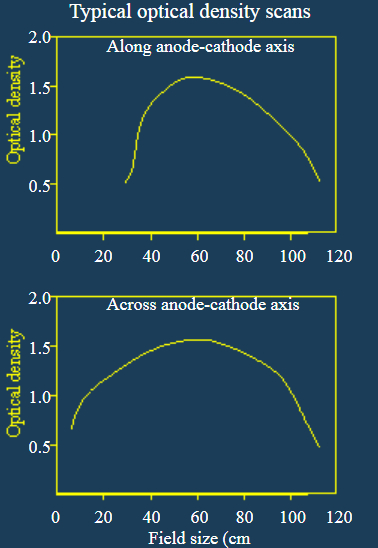
The actual measurement of the air kerma distribution is performed by means of a non-screen film to cover the entire radiation field exposed to obtain a maximum density of between 1 and 1.4 optical density. The exposed and developed film is scanned by means of a densitometer.
Light field X-ray field alignment:
The alignment can be tested by using a simple home-made grid or commercially available test tool:
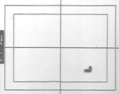
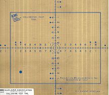
Home-made grid Commercial collimator test tool
The light field is collimated to the same size as the grid and an exposure is made. The developed film will show the deviation of the x-ray field to the light field. The magnitude of the deviation can be calculated by knowing the Focus-Film-Distance. - Automatic exposure control (AEC) functions:
AEC reproducibility:
The reproducibility is evaluated by analysis of multiple test images or exposure measurements obtained at fixed kVp, mA and attenuator thickness.
AEC field sensitivity matching:
The sensitivity matching of the AEC fields and combinations thereof is evaluated by analysis of multiple test images or exposure measurements for each field and combination of fields at fixed kVp, mA and attenuator thickness.
AEC density control selector function:
The ability of the AEC density control selector to allow the intentional variation in image optical density form the normal value is evaluated by analysis of test images and/or milliampere-second (mAs) measurements obtained at each position of the density control selector.
Image receptor field size compensation:
The ability of the AEC system to maintain constant image optical density as a function of image receptor size is evaluated by analysis of test images obtained at a fixed kVp, mA and attenuator thickness.
AEC system performance capability:
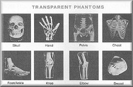
The capability of the AEC system to provide consistent image optical density over a broad range of imaging techniques and attenuator thickness is evaluated by analysis of test images obtained for attenuator thicknesses ranging from 5 cm to 30 cm. - Phantom images
Simulated sectional phantoms can be used to qualitatively evaluate a system’s performance.
1.2.2 Additional Tests for Fluoroscopy Systems
For fluoroscopy systems, additional tests have to be performed to check theperformance of the Image Intensifier (I.I.) and the camera and TV systems. Theseinclude:
- Patient entrance exposure rate:
Patient entrance exposure rates are measured by using ionisation chamber and dosemeter. The minimum Source-I.I. Distance (SID) should be used. Perspex of size 30 x 30 cm, 20 cm thickness is placed near the I.I. to simulate a patient. The chamber is put on top of the phantom at 30 cm from the I.I. The exposures are recorded for every field size and mode of operation. For maximum entrance exposure, the I.I. is cover with at least 3 mm lead to boost the kVp and mA to maximum.Regulation requires that the maximum exposure shall not exceed 10 R per minute. - Automatic brightness control:
Different thicknesses of perspex is placed near the source, activate screening and observed if brightness on the monitor image is maintained. The kVp and mA should be recorded. - High contrast resolution:
Use low kVp (40-60), high input exposure rate, a line pair phantom is placedon the surface of the I.I. and screen. Count the group of line pair that can just be resolved.
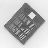
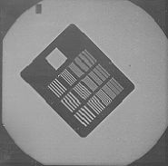
Line pair phantom Line pair image - Low contrast detectability:
A test object, consisting of 19 discs, each of diameter 11 mm, mounted on a perspex plate, is used. The discs produce a range of calibrated x-ray contrasts when used with a calibrated x-ray beam of 70 or 75 kVp. The test object and an image of it are shown below:
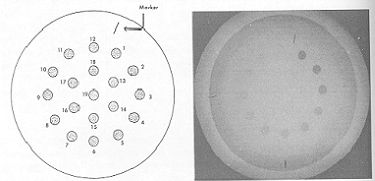
The low contrast detectability can be assessed by counting the number of discs visible in the image during screening. - Image geometry and sizing:
A test object that consists of a wire matrix of 20 mm square spacing with 10 mm diameter interpolations, mounted on a perspex plate, is used. It is positioned as closed to the I.I. as possible but must cover the whole field. An image is then taken with low kVp.
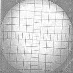
The actual field size can be calculated by the number of squares seen, the source-to-object distance and the source-to-I.I. distance. The ‘S’ distortion can be assessed by visual inspection of the image. The geometric distortion can be quantified by measuring the diagonals of the central square, and of the largest square in the field. - Overall imaging performance:
A test object, consisting of a perspex plate on which metal discs in a range of thickness and diameters, is used. Under calibrated x-ray beam conditions, the object produces calibrated contrasts for the various discs.
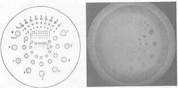
The overall performance can be assessed by counting the number of discs visible for each group.
1.3 Maintenance of X-ray equipment
Responsibility for maintenance of X-ray equipment may lie with the manufacturer, or medical physics services or both. The physicist is therefore prepared to contribute to regular maintenance, usually in an advisory or administrative capacity. Responsibility is also taken for ensuring that the appropriate standards of electrical and mechanical safety are maintained.
1.4 Regular monitoring of equipment
Regular monitoring of equipment, including retake and reject analysis, is necessary to ensure effective operation and image quality. This aspect of quality assurance is undertaken in conjunction with other professions, notably the radiographer. Some of the tests performed in acceptance of the equipment may be repeated to make sure there is no significant deterioration in its performance.
2. Radiation protection
Radiation protection duties involve the measurement and control of doses to patients, staff and member of the general public.
2.1 Protection of the patient
The key to patient protection is the establishment of the relationship between the absorbed dose (and hence the risk) and the benefit which the patient receives as result of the X-ray examination. The physicist contributes by developing and implementing techniques for the derivation of patient dose by direct or retrospective methods and advises on techniques which ensure that doses are as low as reasonably achievable (the ALARA principle). The design and execution of patient dose monitoring is also required.Patient doses can be monitored by means of Dose-Area-Product (DAP) meters or Thermoluminescent dosemeters (TLD).DAP meters use ionisation chambers which can be mounted on the collimator. They measure the dose and multiplied by the area irradiated, which is independent of the distance from the x-ray source. The unit is centi-Gray-centi-meter-square(cGycm²).
 |
 |
| Ionisation chambers | Mounting of the DAP chamber |
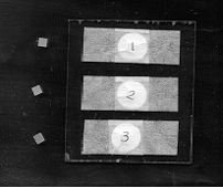
TLDs are tiny crystal (5mm x 5mm x 0.9 mm) which can be packed and stick on surface of the patient. When irradiated, they will store the energy. Upon heating,the stored energy will be released in the form of light which can be detected by a photomultiplier tube. The amount of light is proportional to the energy (dose)stored. The picture below shows the TLD chips and ready pack.
 |
A study has been carried out at the Prince of Wales Hospital to correlate the DAP measurements with the TLD measurements. It was found that for each type of examination, the data correlated very well.
2.2 Protection of members of staff and the general public
The design and mode of operation of X-ray equipment, the nature of the examination and the techniques used all determine the magnitude of the doses to both staff and public. The physicist as RPA (or on behalf of RPA) is involved with:
- The design and layout of X-ray rooms.
- The designation of radiation controlled areas and classified workers.
- The establishment of good working practices.
- The formulation of local rules and systems of works.
- The calibration of radiation measurement equipment.
- The design and execution of dose surveys within the X-ray department.
- The investigation of radiation incidents.
- The provision of a personal dosimetry service.
3. Applied research and development
The physicist continually seeks to improve existing techniques and develop new methods. In particular, digital imaging is quoted as an important and fruitful field of work.
4. Teaching
The physicist provides teaching and instruction for:
- Radiologists undertaking the examination for Fellowship of the Royal College of Radiologists and Hong Kong College of Radiologists.
- Radiographers
- Newly enrolled physicist
- Technicians
- Other staff such nurses, usually in aspects of radiation protection
- Training for RPS
What is Nuclear Medicine?
Nuclear Medicine involves the use of radioisotopes to diagnose and to treat disease. Radioisotopes are utilized in diagnosis as a standard practice for over 60 years. Therapeutic uses (for treating disease) are growing as more treatments methods and more radiopharmaceuticals are developed.
Diagnostic Nuclear Medicine
In nuclear medicine diagnosing techniques, very small amounts of radioactive materials, mostly Tc-99m labeled radiopharmaceuticals, are introduced into the body. Because they are attracted to specific organs, bones or tissues, the gamma emissions produced can provide useful information about a particular type of cancer or disease. Information gathered during a nuclear medicine technique is more comprehensive than other imaging procedures because it describes organ function, not just structure. The result is that many diseases and cancers can be diagnosed much earlier.
Because nuclear medicine procedures utilize very small doses of short-lived isotopes (ones that only remain radioactive for a few hours or days), the amount of radiation received is generally less than or equal to that of an x-ray. Whole body and healthy tissue doses can be minimized while the radioisotope is targeted toward the affected tissue or organ. The main application of nuclear medicine can be summarized as:
- Nuclear medicine uses traces of radioactive materials to image different organs in the body.
- It helps the doctors diagnose disease and measure the function of each organ.
- The amount of radiation involved is small ¡V the dose is similar to that from x-ray investigations.
- It can help find out the cause of pain in bones, chest or the abdomen.
- It can be used to measure how well the heart pumps and how well the kidneys are functioning.
- It can detect infection in the bowels and problems with the blood supply to the lungs.
Therapeutic Nuclear Medicine
Currently the most common therapeutic uses of medical isotopes are for treatment of thyroid cancer, hyperthyroidism, cancer bone pain, and polycythaemia (abnormal increase of red blood cell).
Some of the most exciting cancer treatments utilizing medical isotopes are emerging from current research being conducted on cutting-edge medical applications. As research physicians test these promising radioisotope-based treatments at research hospitals and universities they gradually make their way up the ladder of clinical trials as required for FDA approval.
Certain experimental treatments have had such remarkable success that current cancer sufferers should be made aware of their potential. Lives have been saved in numerous cases of patients with fatal brain tumors, lymphomas and leukemia. In several clinical trials testing experimental treatments, very positive results were achieved on patients who had exhausted all other treatment options with no success.
Central to the progress of new radioisotope treatments has been the invention of unique and effective "delivery systems" which enable physicians to point the selected isotope directly at the diseased tissue. One of the most promising is called radioimmunotherapy. In this technique, radioisotopes are attached to antibodies with a specific affinity for certain cells in the body. The antibodies guide the isotope to the cancer cells where the radioisotope then destroys them.
Nuclear Medicine Physics
Nuclear medicine embodies the successful mixture of basic science and medicine in patient care. Physics, chemistry, pharmacy and computer science are all essentials of nuclear medicine practice. The nuclear medicine physician and technologist must have a working command of these areas and rely on the physicists for optimum patient care.
The very basis of nuclear medicine imaging lies in the discipline of physics. The operation of nuclear medicine equipment is dependent on complex physical principles. Issues of the radiation dose to the patient and workers also fall in the physics area. The optimization of medical imaging parameters for patients as a whole, as well as for individual studies, requires the participation of the physicist. The role a nuclear medicine physicist can be summarized into:
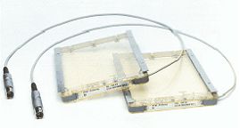
- QA imaging devices, eg, gamma cameras (figure 1) in order to ensure good imaging quality (figure 2), PET, PET/CT (figure 3) to ensure good imaging quality for each modality (figure 4), bone densitometer etc.
- Patient dosimetry, both in vivo and in vitro, for new imaging techniques.
- Provision of radiation protection measurement and calculation.
- Occupational dose monitoring particularly for new imaging techniques.
- Radioactive waste management and documentation.
- Statistical analysis for clinical trial results.
- Educational training in nuclear medicine physics to hospital personnel and to public interest.
- Perform acceptance test to new imaging equipment.
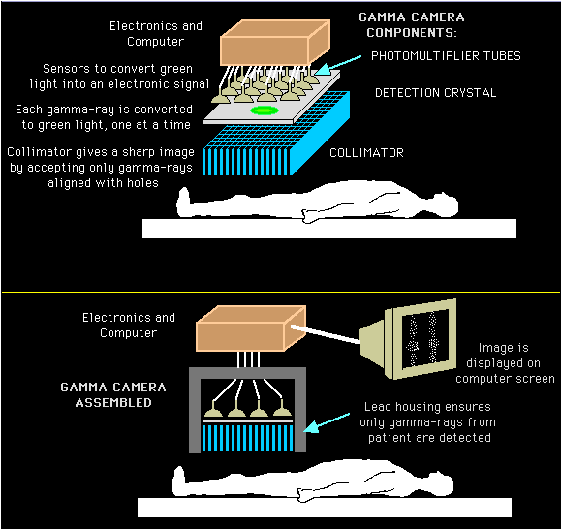 |
| Figure 1: Schematic diagram showing the structure of gamma camera used diagnostic nuclear medicine imaging. |
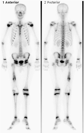 |
| Figure 2: Whole body bone scan images acquired by a gamma camera system. |
About PET/CT
The combination PET/CT scanner is a major advance in imaging technology and patient care.
As the name implies, it combines two scanners ¡V the Positron Emission Tomography (PET), which shows metabolism and the function of cells, and the Computed Tomography (CT), which shows detailed anatomy ¡V into one.
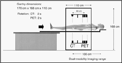 |
| Figure 3: Schematic diagram of a CT/PET scanner. |
The result is that doctors are now able to get highly defined, 3-D images inside the human body in one system. This provides important information about a patient¡¦s condition, and allows doctors to make the best choices about treatment of conditions such as cancer and heart disease.
For example, the PET scanner can provide critical information about the metabolic function of cancer cells, and can detect very small tumors, but not the exact location.
The CT scanner, however, can provide anatomic information. So the combination PET/CT scanner gives doctors a powerful new system for detecting and diagnosing conditions like cancer earlier and more accurately, increasing the patient¡¦s chances of a good outcome.
Another patient benefit of the PET/CT scanner is its open design. This reduces the chances that patients will feel claustrophobic, a complaint many patients have had with scanners that have long tunnels. The PET/CT scanner features two large rings with an open area in between, giving patients the ability to see the area around them and allowing technicians better patient access during the exam.
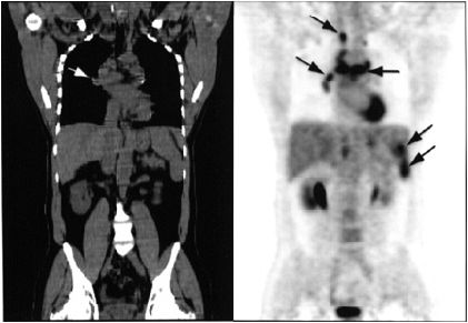 |
| Figure 4. (Left) Coronal CT and (Right) PET images acquired with the PET/CT system in the same patient. Arrows indicate metastatic lesions. The arrows to the right indicate spleen lesions not visualized by CT. |