Notice: Undefined property: stdClass::$thumb in G:\PleskVhosts\hkamp.org\httpdocs\main\templates\flex\sppagebuilder\addons\gallery\site.php on line 46
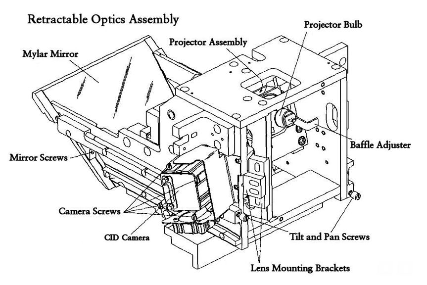
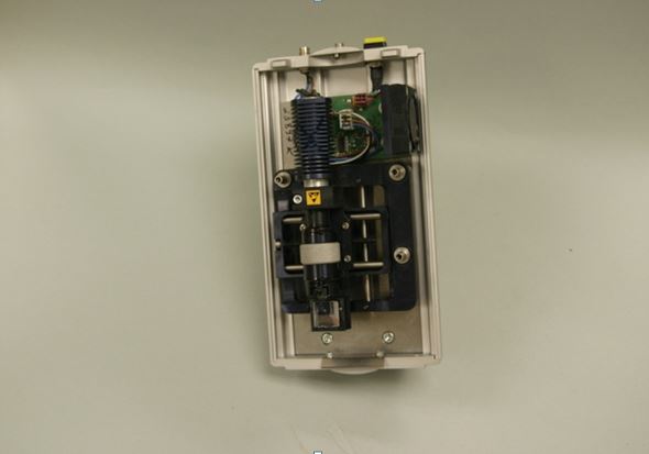
Iridium-192 Model of Interstitial Implant (Manual) Using Iridium-192 Hairpin in Brachytherapy Charge Injection Device Cameras (CID) MLC Motor Ionization Chamber Thyratron Potentiometer Magnetron Mode Transformer Ion Pump Flight Tube in Bending Magnet Section Electron Gun Room Laser Mylar Mirror Carousel
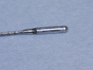
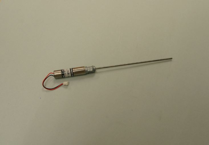
Ir-192 implants have medical uses in healthcare industry. These are used for curative reasons, primarily in the breast and the head. These implants are manufactured in wire form and are introduced into the target area through a catheter. The implant wire is removed after being left in place for the time required to deliver the desired dose. This procedure is very effective at providing localized radiation to the tumor site while minimizing the patient’s whole body dose.
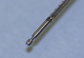
Thick Iridium wires, 0.6 mm in diameter, in the form of hairpin can be inserted directly into tumors through suitable introducers.
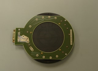
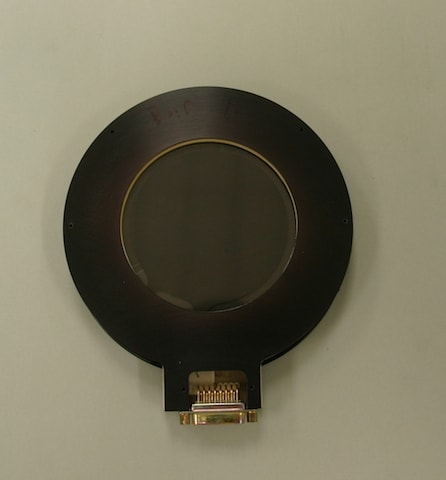
Charge Injection Device (CID) cameras have been in use since the early 1970's. The CID concept was originated by scientists at General Electric Company working to devise a semiconductor memory chip. Exploiting the photosensitive characteristics of silicon, they developed a simple X,Y addressable array of photosensitive capacitor elements, and evolved the first CID camera in 1972.
Every pixel in a CID array can be individually addressed via electrical indexing of row and column electrodes. Charge does not transfer from site to site in the CID array. Instead, a displacement current proportional to the stored signal charge is read when charge "packets" are shifted between capacitors within individually selected pixels. The displacement current is amplified, converted to a voltage, and fed to the outside world as part of a composite video signal or digitized signal. Readout is non-destructive because the charge remains intact in the pixel after the signal level has been determined. To clear the array for new frame integration, the row and column electrodes in each pixel are momentarily switched to ground releasing, or "injecting" the charge into the substrate.
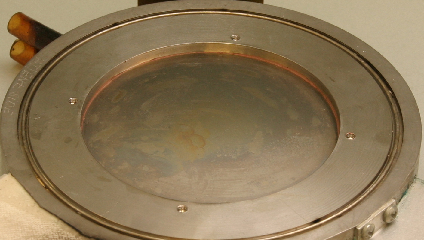
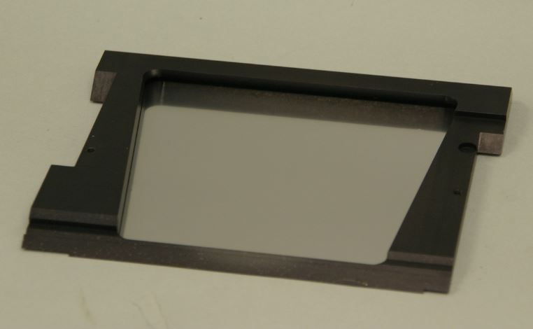
Elekta's ionization chamber is a beam monitoring device used to measure radiation. The chamber air is vented , so its response is influenced by atmospheric temperature and pressure.

Elekta's ionization chamber is a beam monitoring device used to measure radiation. The chamber air is sealed , so its response does not influenced by atmospheric temperature and pressure.

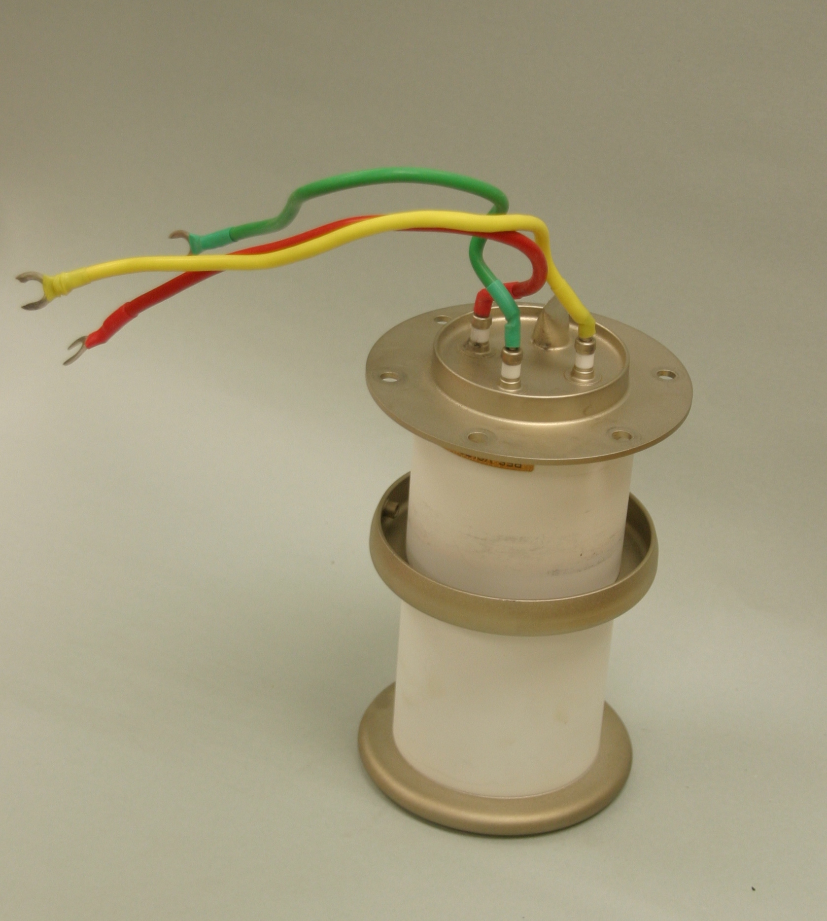
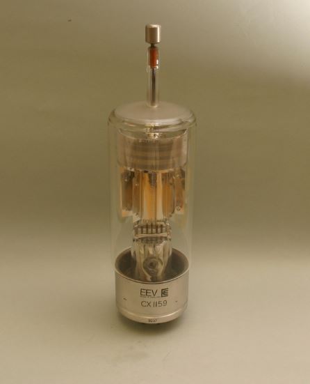
Thyratron is a gas-filled discharge chamber that contains a cathode filament, an anode plate, and one or more grids. An inert gas or metal vapor fills the discharge chamber. The grid controls only the starting of a current and thus provides a trigger effect. The normal grid potential is negative with respect to the cathode and prevents electrons from flowing to the plate and exciting a discharge. To cause a discharge, the grid potential is raised enough to start electrons flowing from the cathode. As free electrons stream toward the plate, they collide with gas molecules, freeing other electrons and ionizing the gas within the discharge chamber. When a sufficient number of ions and electrons are present, a “short” occurs, and a large current flows from the cathode to the plate, causing a discharge. The discharge can take place in a few hundred-millionths of a second. The discharge stops when the anode voltage has been sufficiently lowered. Thyratron tubes are used typically in radar pulse modulators, particle accelerators, lasers, and high-voltage medical equipment.
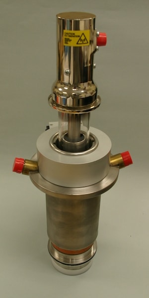
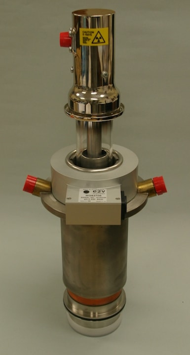
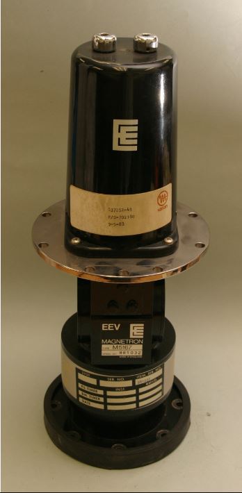
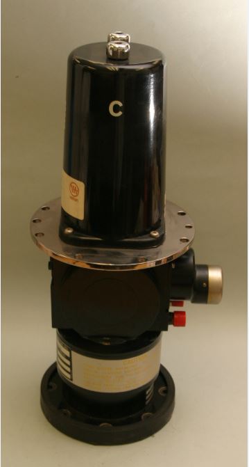
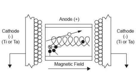
The magnetron consists of a cylindrical cathode, heated by a filament, surrounded by a resonant cavity anode structure. This is mounted inside the magnetron magnet which is an electromagnetic coil. The magnetron filament voltage is controlled by software to maintain the cathode temperature to supply a constant number of electrons. High voltage pulse is applied to the magnetron cathode. The negative pulse emits electrons from the cathode towards the anode. Due to the electromagnetic field from the magnetron magnet, the electrons are forced to follow a curved path between the cathode and anode. The passage of the electrons past the cavities causes a build up of radio frequency. The frequency of the RF generated by the magnetron is determined by the cavity dimensions. As the magnetron is pulsed, the anode structure heats and thus expands causing a charge in frequency. To maintain a constant frequency, the volume of the cavity is controlled by inserting tuning fingers. The operating frequency is controlled by a combination of software and electronics.
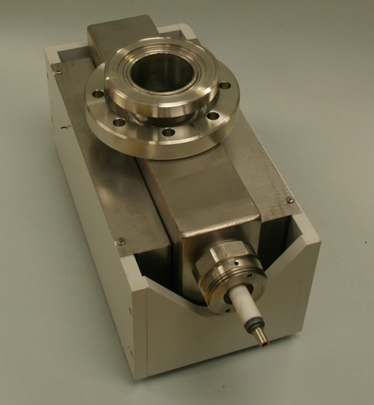
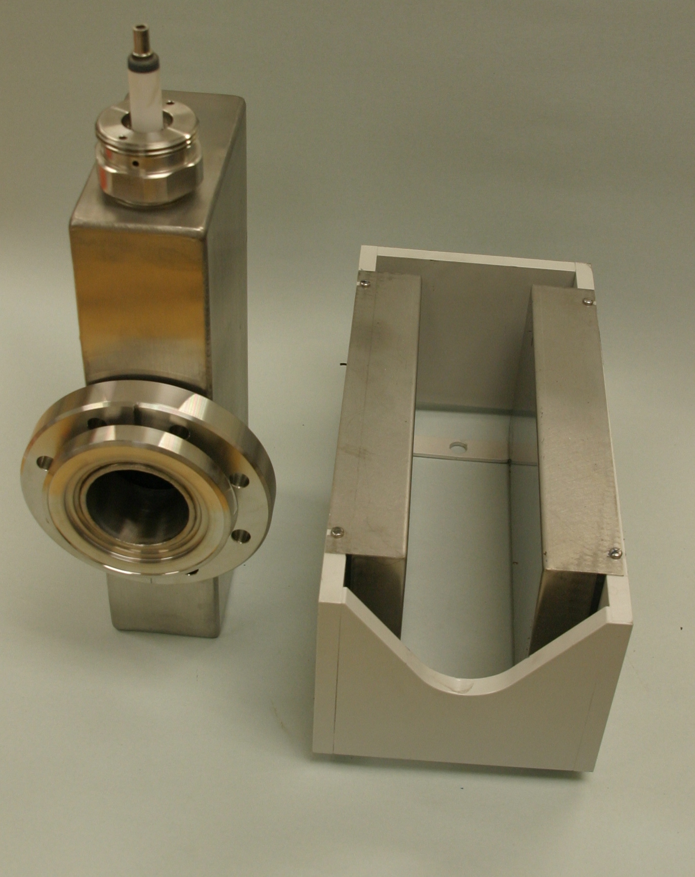
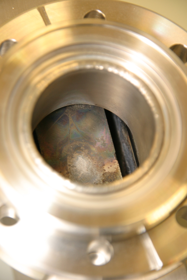
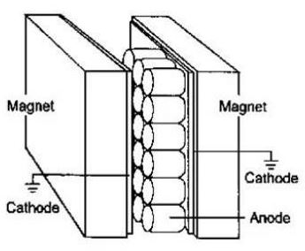
The pump consists of two flat rectangular cathodes with an anode between them made up of large number of open ended tubes.
A permant magnet surrounds the pump. Th power supply provides -5kV to the anode with the cathodes at ground.
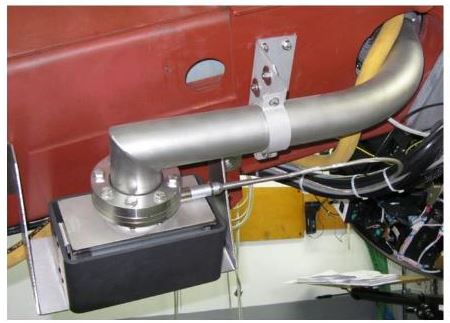
Electrons from the cathode move towards the anode and move in a circular motion due to the magnetic field, resulting in increased probability that the electrons will collide with gas molecules that enter the pump from the circular waveguide.
The collisions produce positive ions which are captures on the cathodes. As the ionds collide with the cathodes, more electrons are emitted and the process continues.
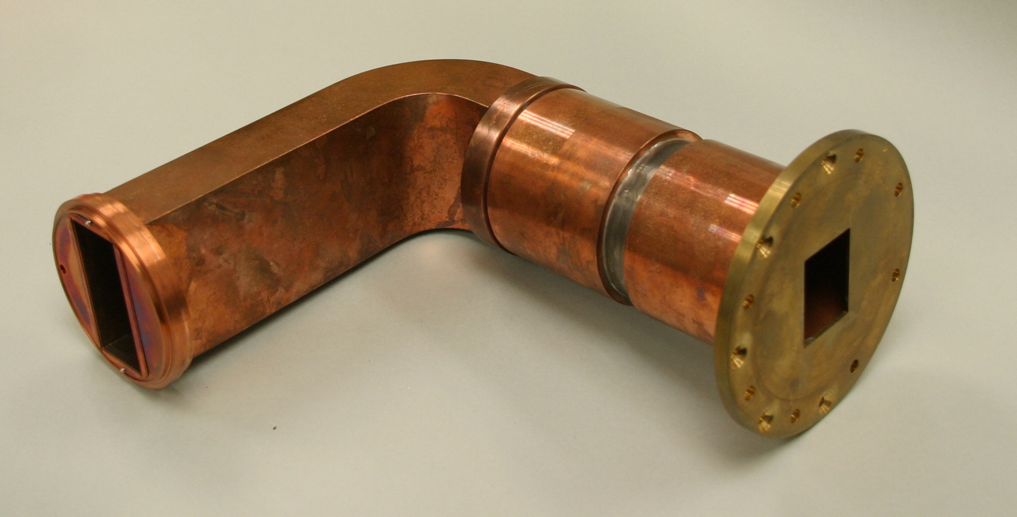
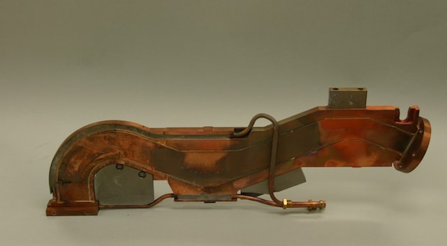
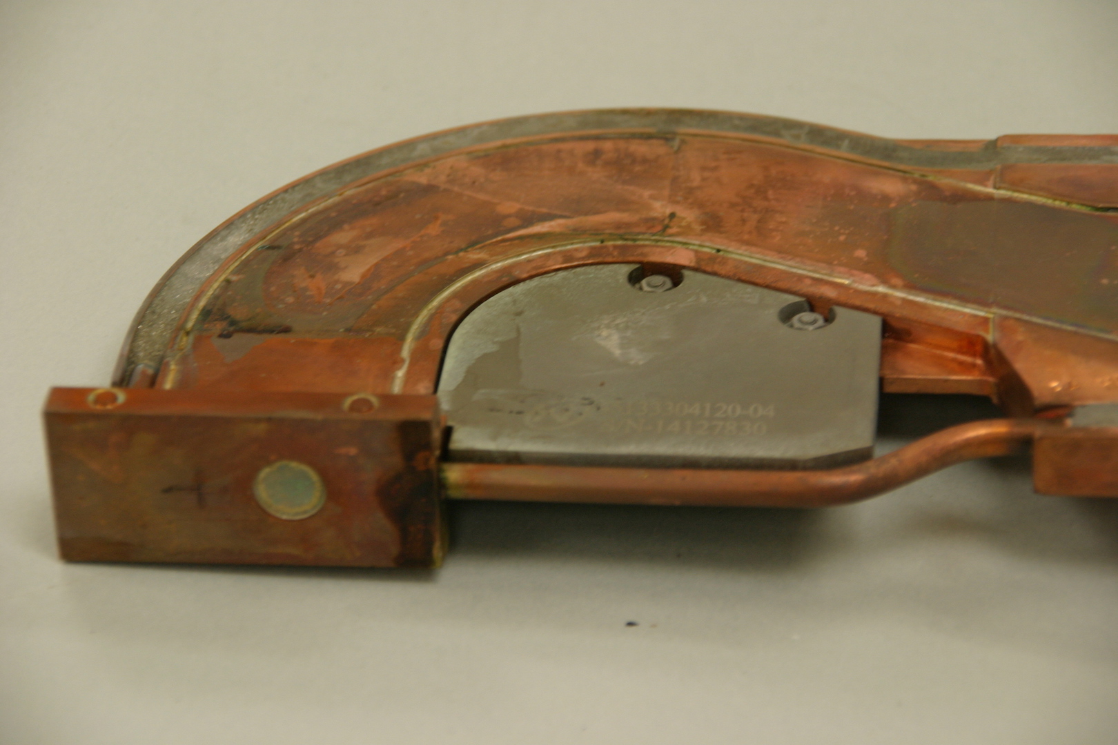
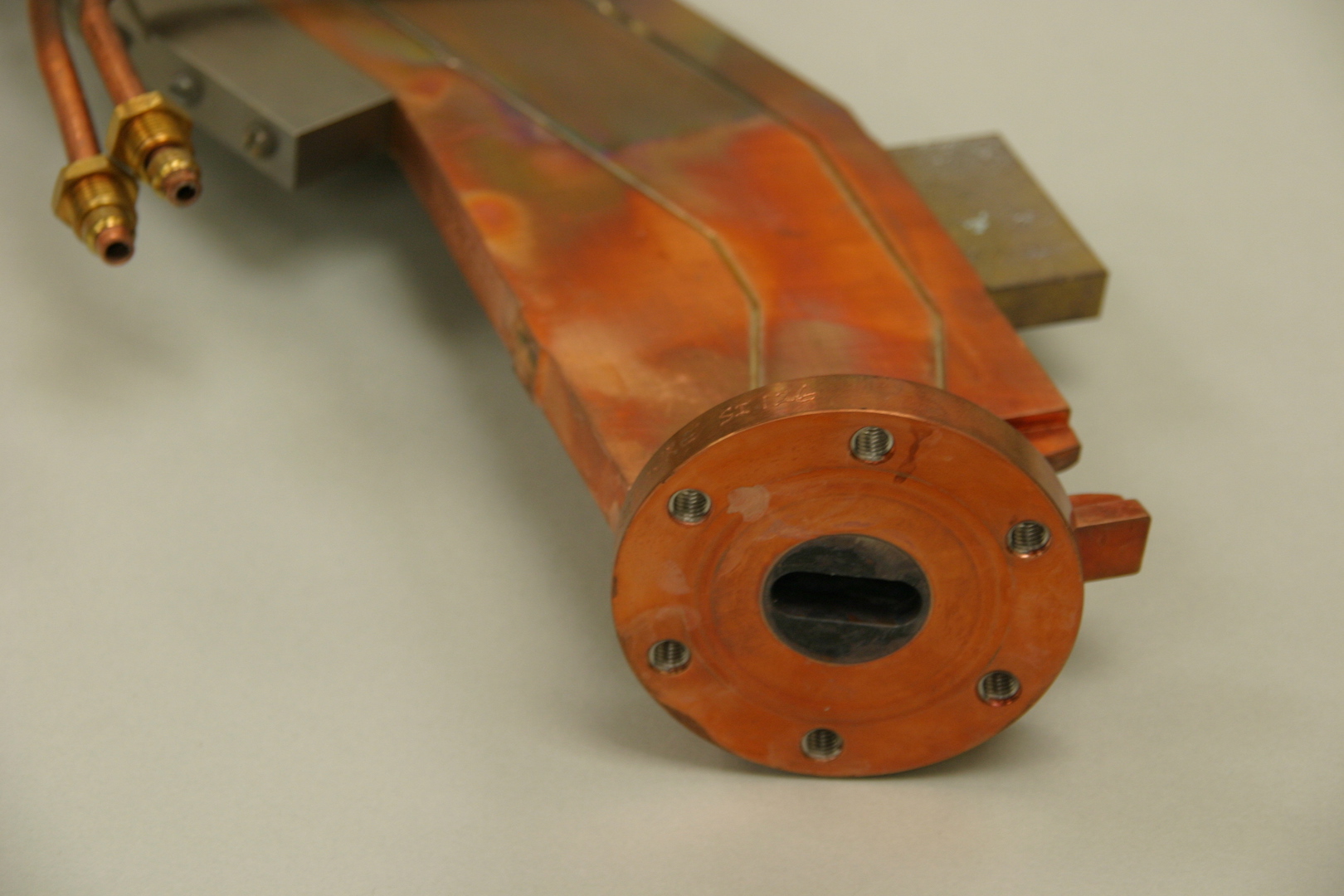
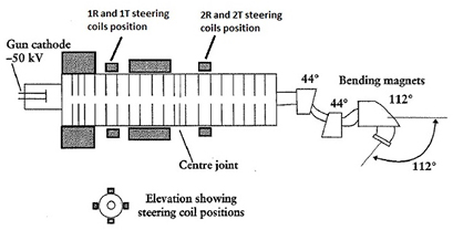
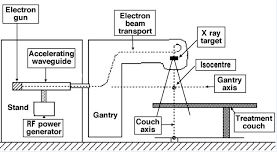
This is the flight tube in the beam bending system which is used to control the electron beam through to the flight tube and target after the electron acceleration process.
On emerging from the waveguide, the electron beam passes through a bellows section. The bellows allow the entire flight tube assembly to be moved within the beam beading system by a mechanism known as the target shift, whilst still maintaining the vacuum in the accelerating waveguide.
From the bellows, the electron beam is transported through the beam bending system comprising an achromatic triple magnet array in an evacuated flight tube. The magnet array provides double focusing of the electron beam. Under its influence, the beam is deflected through 112 degrees ( from 22 degrees above horizontal to 90 degrees below).
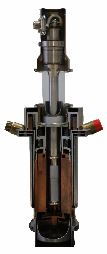
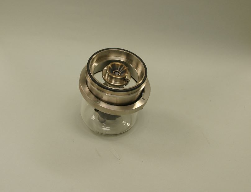
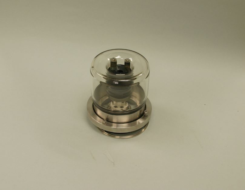
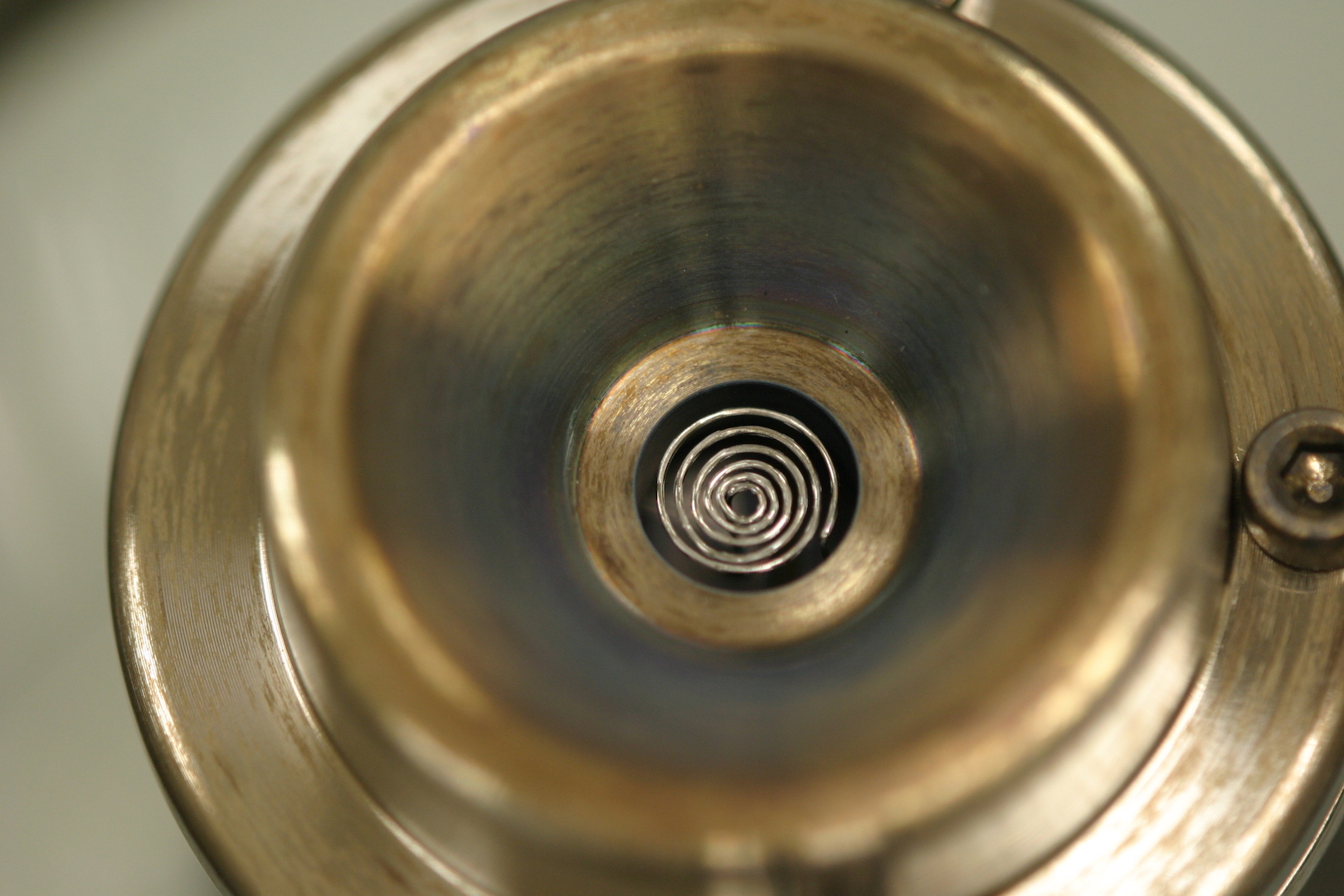
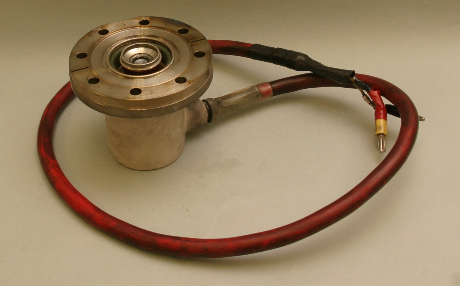
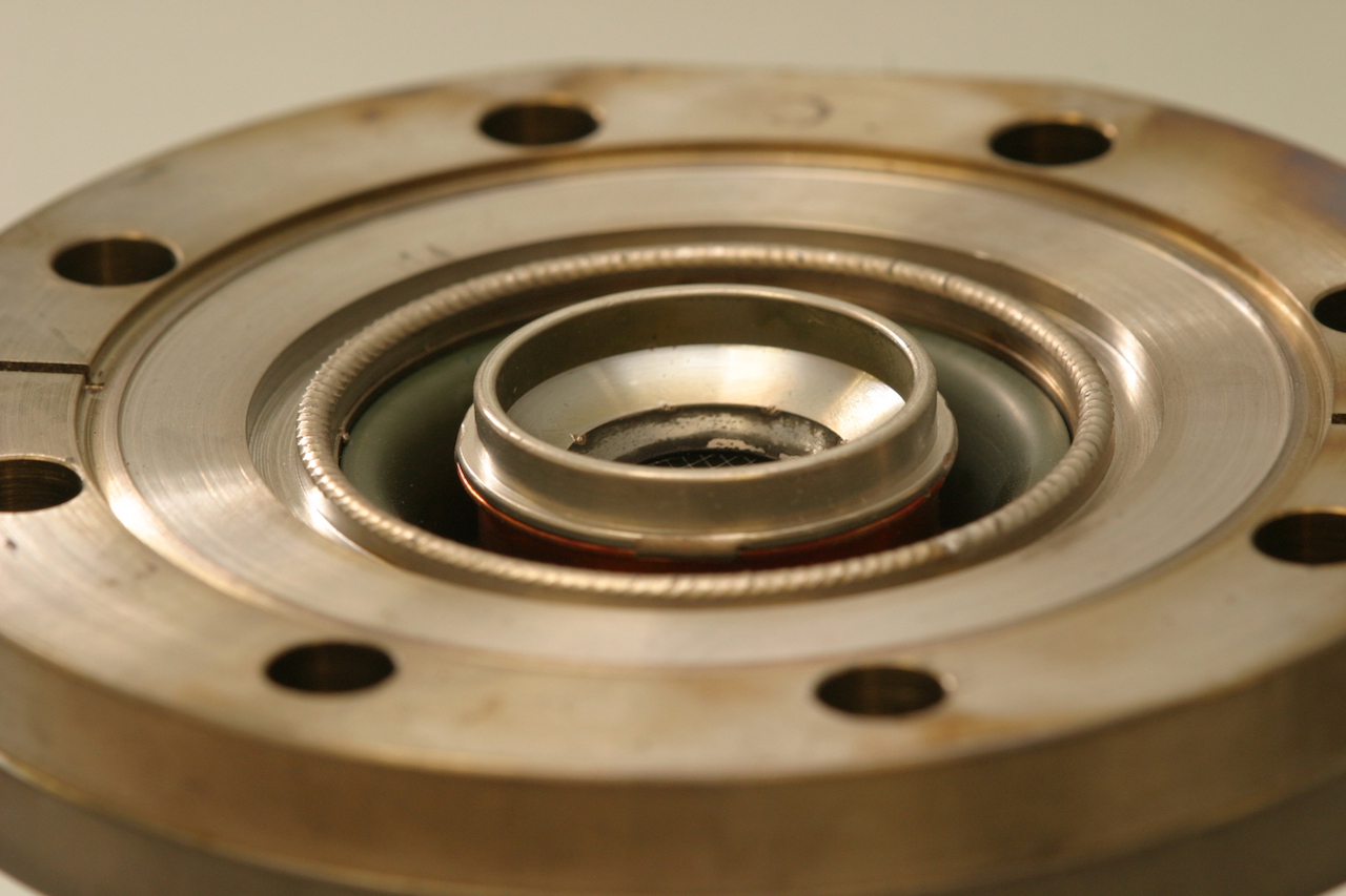
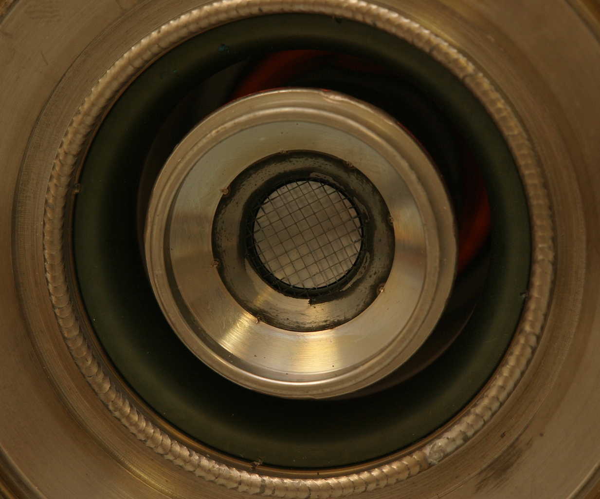
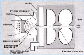
The electron gun, located at the left in the drawing, is where electron acceleration begins. The electrons start out attached to the molecules in a one-cubic-centimeter chunk of barium aluminate. This is the cathode of the electron gun. A cathode is a surface that has a negative electrical charge. In linac electron guns this charge is usually created by heating the cathode. Barium aluminate is a "thermionic" material; this means that it's electrons tend to break free of their atoms when heated. These electrons "boil" near the surface of the cathode.
The gate is like a switch. It consists of a copper screen, or "grid," and is an anode. An anode is a surface with a positive electrical charge. Every 500 millionth of a second the gate is given a strong positive charge that causes electrons to fly toward it from the cathode in tremendous numbers. As these electrons reach the gate, they become attracted even more strongly by the main anode, and pass through the gate.
Because the gate is pulsing at a rate of 500 million times per second (500 MHz), the electrons arrive at the anode in loose bunches, a 500 millionth of a second apart. The anode is a torus (a doughnut) shaped to create an electromagnetic field that guides most of the electrons through the hole into the next part of the accelerator, called the buncher.
Room laser is used to ensure the patient is in the proper position. The accuracy of the laser guides in determining the isocenter position. Isocenter is a virtual point where the rotational axis of ganry, collimator and couch meets. 2 Sides lasers, sagittal and ceiling lasers are mounted on walls of bunker.
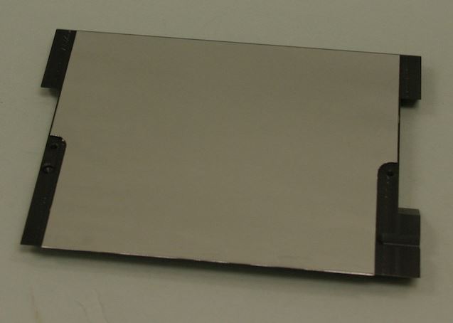
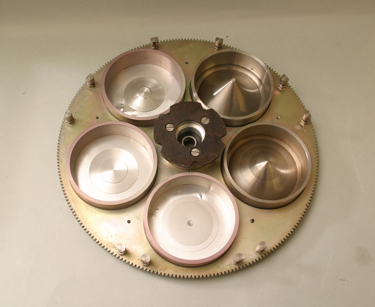
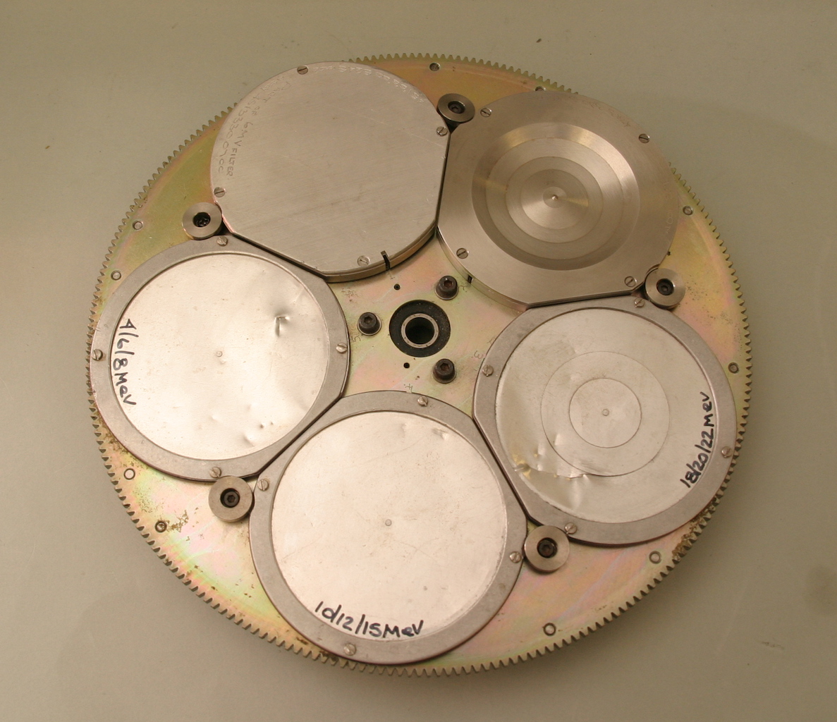
The carousel in the linac holds flattening filters and scattering foil. As the photon dose distribution produced by a linac is strongly forward peaked,a flattening filter is inserted in the beam. The flattening filter can make the beam intensity uniform across the field by reducing the central exposure rate relative to that near the edge of the beam. The filter is usually made of copper or brass.